
The role of washing machine control board explained
2026-07-27 15:59:24
What does the washing machine control board actually do?
The control board acts as the central processor, managing communications between every subsystem in the machine simultaneously. When you select a wash programme and press start, it receives that input, interprets it, and begins issuing instructions to each connected component in the correct sequence. Water intake, drum rotation, temperature regulation, and drainage all happen because the board is orchestrating them in real time.
Its primary roles include:
Executing wash, rinse, and spin cycles according to the selected programme
Controlling motor speed and direction throughout each phase
Managing water intake and drainage via solenoid valves
Regulating water temperature through continuous sensor feedback
Monitoring water level, load weight, and drum position sensors
Displaying operating status and error codes on the user interface
Providing safety protections against overcurrent, overvoltage, and overheating
The key hardware terms you will encounter when researching this component are: the motor module, display module, power module, electronic card, and motherboard (or main board). These terms are often used interchangeably in repair guides, though they refer to distinct physical parts of the overall control system.
What are the main components inside the control board module?
The core of the control board is a microprocessor, which receives instructions from the control panel and signals from sensors, then outputs the corresponding commands to motors and valves. Surrounding it are several supporting components, each with a specific function.
Microprocessor: The central control unit that processes all input signals and executes predefined washing programmes.
Memory modules: Store the machine’s software, user settings, and operational data, including saved error codes.
Input/output interfaces: Connect the board to user controls, sensors, and other electronic components throughout the machine.
Power supply circuit: Converts incoming AC mains power to the DC voltages required by the board’s electronic components.
Clock circuit: Maintains precise system timing, ensuring wash cycles, delays, and component activations are synchronised correctly.
Motor module: The dedicated circuit responsible for driving and regulating the main drive motor.
Display module: Manages communication with the user interface panel, indicator lights, and any LCD or LED display.
Electronic card / motherboard: The physical printed circuit board on which all the above components are mounted and interconnected.
These components interact by passing electrical signals along conductive tracks on the board. A fault in any single component can disrupt the entire chain of communication, which is why board-level diagnosis requires a methodical approach rather than guesswork.
Which functions does the control board manage during a wash cycle?
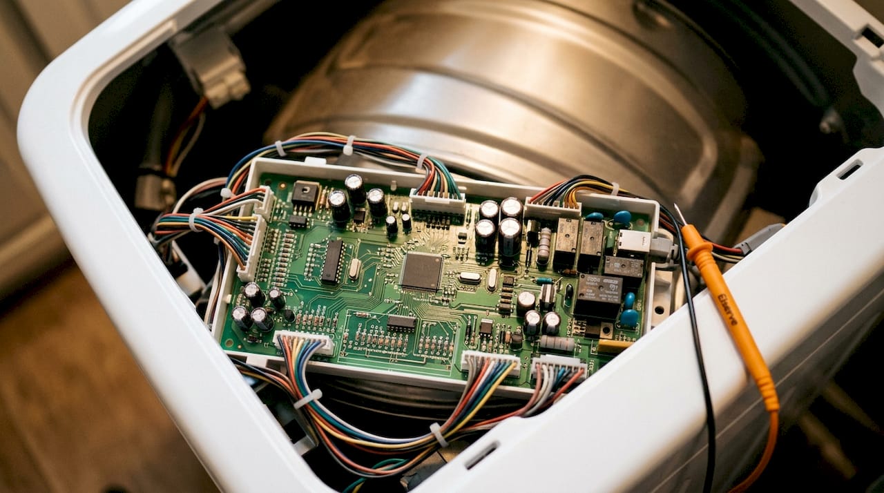
The board’s responsibilities extend well beyond simply switching the machine on and off. Each phase of a wash cycle depends on a distinct set of control board instructions.
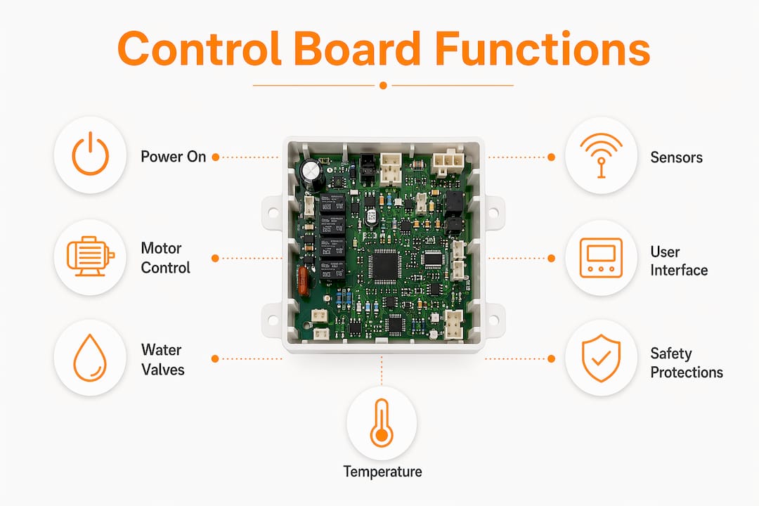
Motor control is perhaps the most demanding task. The board adjusts motor speed and direction continuously, producing the gentle agitation of a delicate cycle or the high-speed spin of a cotton programme. Modern control boards allow variable speed control, which reduces mechanical wear over time.
Water intake and drainage are managed through solenoid valves. The board opens and closes these valves at precise moments, controlling how much water enters the drum and when it is expelled. A fault here can cause overfilling, underfilling, or a drum that refuses to drain.
Temperature regulation relies on a thermistor or NTC sensor feeding live readings back to the board. If the water temperature deviates from the target, the board adjusts the heating element accordingly. Without accurate sensor feedback, the machine may wash in cold water while displaying the correct temperature, or overheat the load entirely.
Sensor monitoring runs continuously throughout the cycle. The board tracks water level via a pressure sensor, load weight through motor current draw, and drum position using a hall-effect sensor or tachometer. Real-time adjustments based on this data are what allow modern machines to adapt to different load sizes automatically.
User interface management covers the display panel, button inputs, and error code generation. When you press a button, the signal travels to the board, which processes the instruction and updates the display accordingly.

Safety protections are built directly into the board’s firmware. The PCB incorporates overcurrent, overvoltage, undervoltage, and overheating protection, triggering an automatic shutdown if any parameter exceeds safe limits. This is not a passive feature; the board actively monitors these parameters throughout every cycle.
How do you recognise signs of control board failure?
A failing control board tends to produce symptoms across multiple systems at once, precisely because it governs all of them. A single board failure can cause the drum to stop spinning, water to stop draining, and error codes to appear simultaneously, which is what makes these faults so difficult to attribute at first glance.
The most common indicators include:
Failure to power on: The machine shows no response when the power button is pressed, despite a confirmed mains supply.
Mid-cycle stoppages: The machine halts unexpectedly during washing, rinsing, or spinning without completing the programme.
Persistent error codes: Fault codes appear on the display and cannot be cleared by a standard reset or power cycle.
Erratic panel behaviour: Buttons become unresponsive, or the display shows garbled characters and incorrect status information.
Burnt smell or visible scorch marks: Physical evidence of heat damage on or near the board area, often accompanied by a distinct electrical burning odour.
Multiple simultaneous faults: Several unrelated functions failing within the same cycle is a particularly telling pattern.
Pro Tip: Before concluding that the control board has failed, check whether the symptoms appeared immediately after a power cut or electrical storm. Power surges are among the most common causes of board damage, and a surge protector rated for appliance use can prevent recurrence after a replacement.
How do you diagnose control board problems step by step?
Systematic diagnosis prevents the costly mistake of replacing a board that was never the root cause. Professional technicians use a structured sequence of checks, moving from the simplest possible cause to the most complex.
Confirm the power supply. Verify that the wall socket is live using a known working appliance or a multimeter. Check the machine’s power cord for visible damage and confirm the circuit breaker has not tripped.
Perform a hard reset. Unplug the machine for five minutes, then reconnect. This clears temporary software faults and can resolve intermittent error codes that are not caused by hardware failure.
Record all error codes. Note every fault code displayed before and after the reset. These codes are the board’s own diagnostic output and point directly to the subsystem where the fault was detected.
Enter the machine’s service diagnostic mode. Modern washing machines include a built-in service mode that allows targeted testing of individual components, including valves, pumps, and sensors, without specialist equipment. The activation sequence varies by manufacturer and is usually documented in the tech sheet for the model.
Use a multimeter to check input voltage. Measure the voltage reaching the control board from the mains supply. If the board is receiving correct voltage but not responding, the fault is more likely internal to the board itself.
Inspect wiring harnesses and connectors. Oxidised or loose connector pins are a frequent cause of intermittent faults that mimic board failure. Reseat every connector firmly and look for signs of corrosion, chafing, or heat damage on the wiring.
Test peripheral components individually. Check the door latch switch, water level pressure sensor, thermistor, and motor before concluding the board is at fault. A short circuit in any peripheral component can produce symptoms that appear to originate from the board.
Conduct a visual inspection of the board itself. Look for burnt components, swollen capacitors, cracked solder joints, and scorch marks on the PCB surface. Physical damage of this kind confirms board failure rather than a peripheral fault.
Pro Tip: Diagnostic modes expose fault codes and enable individual component activation, allowing you to test valves, pumps, and sensors one at a time. This targeted approach avoids the expense of replacing components that are actually functioning correctly.
Professional insights on maintaining and troubleshooting the control board
Experienced appliance technicians consistently observe that the majority of apparent control board failures turn out to be communication faults or peripheral sensor issues. Replacing the board without first ruling out these causes wastes money and, in some cases, damages the new board through the same unresolved root cause.
The four most common causes of genuine board failure are worth understanding before any repair decision:
Power surges: A voltage spike from a lightning strike or a switching event on the mains supply can destroy relay components, blow protection diodes, or burn capacitor legs almost instantly. The damage may be immediately visible as a scorch mark, or it may cause progressive relay degradation over subsequent weeks.
Moisture intrusion: Water reaching the board, whether from a slow hose leak, a failed door seal, or overfilling caused by a faulty pressure switch, causes immediate shorts between conductive tracks and long-term corrosion on connector pins.
Relay wear from overloading: The board contains power relays that switch high current to the motor, drain pump, and inlet valves. Consistently overloading the machine beyond its rated capacity causes relay contacts to arc and pit over time, eventually causing a component to run continuously or stop working.
EEPROM data corruption: The board stores its operating programme in a non-volatile EEPROM chip. A power interruption at a critical moment during a write cycle can corrupt this data, generating fault codes that persist even after a reset.
Safety precautions are non-negotiable when handling or testing a control board. Always disconnect the machine from the mains supply before opening the cabinet or touching any internal component. Even after disconnecting, capacitors on the board can retain a charge; allow at least two minutes before making contact. Never operate the machine with the cabinet open or with any connector deliberately disconnected, as this can damage the board or create an electrical hazard.
The question of whether to repair or replace the board depends on the nature of the fault and the age of the appliance. A board with a single failed relay or a damaged capacitor can often be repaired at a fraction of the replacement cost, whereas a board with extensive track damage or a corrupted EEPROM may be more economical to replace outright. For a detailed real-world example of how these decisions play out in practice, the diagnostic case study from Omega Force Appliance Repair illustrates how a methodical approach changes the outcome. Similarly, their control board troubleshooting case study demonstrates how peripheral faults are identified and separated from genuine board failure before any parts are ordered.
If you are based in London and the diagnosis points to a control board fault, professional appliance repair from Elserve covers washing machine electronics with two-hour appointment slots, avoiding the delay and uncertainty of self-diagnosis on a complex fault.
Key takeaways
The washing machine control board governs every function of the appliance, and a systematic diagnostic approach is the only reliable way to confirm whether the board itself or a peripheral component is at fault.
| Point | Details |
|---|---|
| Central role of the board | The control board coordinates motor, water intake, temperature, sensors, and safety protections simultaneously. |
| Most failures are not the board | Peripheral sensor faults, loose connectors, and wiring issues frequently mimic control board failure. |
| Power surges cause most genuine failures | Voltage spikes, moisture intrusion, relay wear, and EEPROM corruption are the leading causes of real board damage. |
| Diagnostic mode is your first tool | Built-in service modes allow individual component testing without specialist equipment, narrowing the fault before any part is replaced. |
| Repair versus replace depends on fault type | A single failed relay or capacitor is often repairable; extensive track damage or EEPROM corruption usually warrants full board replacement. |
Recommended
Recent Post

Why your washing machine trips the fuse: what to check
2026-10-24 16:36:57
_(2)_(1).png)
Elserve Featured by USA News for Trusted Appliance Repairs in London
2026-10-18 17:01:41

Act Fast: Signs of Faulty Wiring in London Homes, £42 Diagnostics
2026-10-10 08:12:45
 Looking for a fast and reliable appliance repair service?




ELSERVE is a registered company in England. Registered number 09798443. VAT number 407675383
Some images used on this website are stock photographs used for illustrative purposes only and may not depict ELSERVE employees, customers, or actual service visits



-
Why your washing machine trips the fuse: what to check
2026-10-24 16:36:57
-
Elserve Featured by USA News for Trusted Appliance Repairs in London
2026-10-18 17:01:41
-
Act Fast: Signs of Faulty Wiring in London Homes, £42 Diagnostics
2026-10-10 08:12:45